Halloween Milling
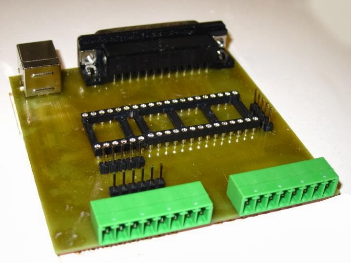
A few years ago I bought a cheap CNC mill from China. It’s actually a “CNC engraving machine”, but it’s actually robust enough so that it can mill wood and soft metals such as aluminum. Ḯ’ve been using it to build electronics prototypes, both for milling PCBs and for milling enclosures.
To control the CNC mill I have been using LinuxCNC (formerly known as EMC2). LinuxCNC takes a toolpath written in G-code which says how the milling tool should move, and translates those into the electronic signals that drive the motors on the mill.
For PCB milling I’ve been using a tool called pcb2gcodewhich takes gerber files produced by a PCB CAD program such as Eagle and produces G-code. It works really well and makes it possible to quickly testing simple electronic designs.
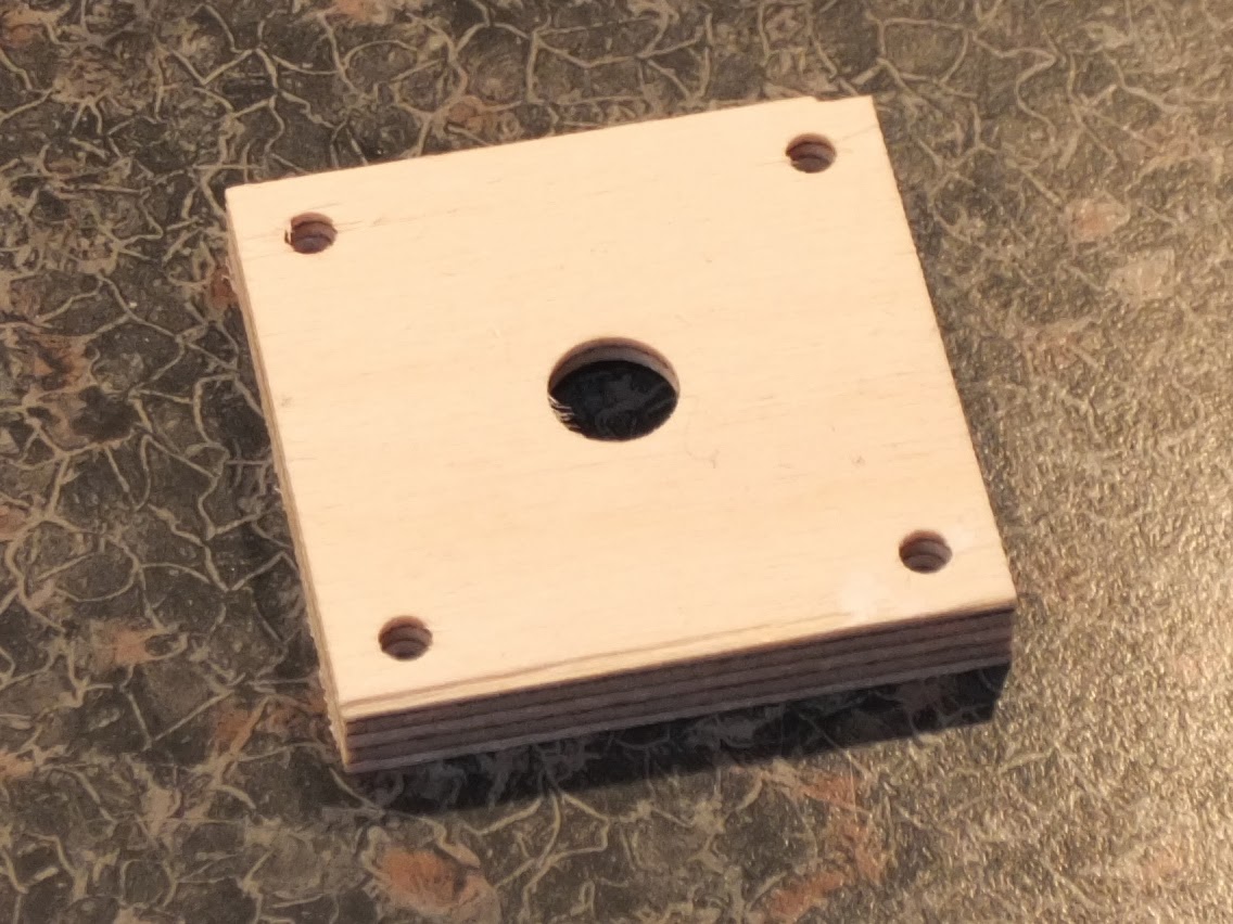
For enclosures I have mostly been bying ready-made enclosures and then written a bit of G-code by hand to mill holes in them. I’ve also been milling wood and plastics for simple stuff such as this lid.
Writing G-code by hand is a very tedious job, anything more complicated than a few holes requires a lot of work. There are a lot of tools and meta- languages for generating G-code from other languages. I wrote my own little Python library for generating G-code and it turns out that the Axis GUI for LinuxCNC can actually load and run Python programs and execute the G-codes that are printed by the program. But even with all these tools or meta- languages it’s still quite tedious to generate the toolpaths by hand.
It would be even nicer if there was a way to create a 3D model in a tool such as OpenSCAD or Blender and then magically let a tool generate G-code, a toolpath which tells the mill how the tool should move to create a physical object which looks like the model. Most 3D modeling tools can export to a standardised interchange format called STL and there are lots of tools which can read STL and generate toolpaths.
Most of these tools are proprietary though and the cost ranges from expensive to insanely expensive. Most of them only run on Windows and I prefer to use Linux and anyway I like open source, so I would prefer to use an open source toolpath generator if possible. There are a bunch of those, but most are at the “alpha” level and nowhere close to being usable. The most mature open source toolpath generator I have found is PyCAM. Unfortunately PyCAM and I don’t really get along, I don’t like the toolpaths it generates and last time I tried, it was really, really slow. My guess is that one for PyCAM being so slow is that it tries to be very generic and handle models and milling tools of almost any shape. Algorithms to calculate a toolpath for an abitrary 3D shape around an arbitrary 3D model are complex and expensive.
For a long time there have been this thoght at the back of my head that “there must be an easier way”. For almost everything I want to mill, I’m going to use a cylindrical tool. With a cylindrical milling tool, the toolpath generation problem is reduced to 2.5D, that is, for each position X and Y the tool is allowed to reach a certain depth Z. This 2.D problem ought to be a lot easier to solve than the generic 3D problem.
A fairly simple strategy of milling 2.5D shapes would be to slice up the 3D model into 2D layers. The algorithm would then start from the top, and remove material for each 2D layer until there is no more material to remove. This is called waterline machining. It might not be the fastest way to things, but it should be fairly foolproof.
For removing material there are lots of ways to do it. The simplest way is to just move back and forth in a zig-zag pattern. But there are much better ways to do it, to reduce the wear on the milling tool it’s preferable to keep a constant load on the tool, i.e. cut with the same side of the tool at the same depth and at the same speed all the time. The most important thing is to avoid is rapid load changes such as cutting 90 degrees into a wal. This article att BobCAD-CAM shows some of the toolpah options that used. Option 3, the High Speed Machining (HSM) toolpath, is the best since it avoids any sharp corners and each cut is very smooth.
I have been toying with algorithms like these for a few years but have never gotten anywhere. But a few weeks ago just before Halloween I tried a slightly different approach. The goal was to find an algorithm which would remove material from a 2D outline and do it using the same side of the tool to perform all cuts and which would try to keep the cuts at a constant width.
What I did was to split the toolpath generation into four steps.
-
Take the model and shrink it by the milling tool radius. This way the algorithm can ignore the tool with for the rest of the calculations, instead it only have think about where the tool can move.
-
Find the center of largest circle that can be inscribed in the model. To do this just shrink the model until there is nothing left and use the center of the last polygon as the starting point.
-
Start cutting a spiral from the starting point outwards until the spiral intersects the outline. For each 360 degree turn the radius of the spiral grows by the cut width.
-
Cut away the rest of the material. Start by creating a polygon with the the material that has already been cut away, this will roughly be the convex hull of the spiral. Grow the polygon by the cut width and then clip it with the model. The difference between the polygon of already removed material and the grown and clipped polygon are a number of polygons with material that is possible to remove. Choose one of them, mill away the material, add the polygon of just removed material to the big polygon of removed material and start over again until there is no more material to remove.
I started out by using the Python port of the Clipper library to do the shrinking, growing and clipping but switched to Shapely after a while because I needed some function that wasn’t available in Clipper. A function that I ended up not using in the end anyway, but by then I couldn’t be bothered to switch back.
This actually turned out to work quite well. Because it was Halloween I decided to do a small test with a witch silhouette I found. I converted it by hand from SVG to a bunch of coordinates (and managed to flip the image horizontally and lose a few parts of the broom on the way).
The following video shows the algorithm running.
Since this seemed to work so well I quickly added some functions to generate G-code and then used LinuxCNC to run the G-code on the mill. And what do you know, it actually worked quite well.
The video is speeded up 10 times, in real life it took about 20 minutes to run. The algorithm video and the actual milling video differ a bit in the cuts since I tweaked the algorithm slightly in between.
Of course this is just a quick proof of concept hack to see if the algorithm would work at fall, but it does look rather promising.
There are lots of things to do though to bang this into shape so that it is actually useful.
The algorithm makes a few mistakes where removes too much material at the same time. It really should try to find a way of smoothly moving into each cut.
The algorithm does not support multiple pockets or pockets with holes.
The algorithm only cuts one layer in 2D, to be useful for milling it needs to be extended to 2.5D.
Yet another pre alpha not even close to production ready piece of software for generating toolpaths. Probably not that interesting, but if anyone wants to see the source code, drop me a line.