A TDR scope
I’ve gone and bought an old oscilloscope, a Tektronix 11801B. The 11801 is a 20 year old design, but it still has some pretty impressive specifications: 50GHz analog bandwidth and takes a sample in 10fs (yes, femtoseconds). With the scope I got a SD-24 sampling module which only has 20GHz bandwidth but it also has a pulse generator to make TDR measurements.
So what is TDR? It is an acronym for “Time Domain Reflectometry”. What it means is that the scope generates a really fast voltage pulse into a cable and at the same time it is sampling the voltage at the source and showing how the voltage changes over time. With an infinitely long perfect cable the pulse will travel along the cable forever, but in many cases there are imperfections in the cable that reflect the pulse back to the source and change the shape of the signal seen there.
There are lots of articles about TDR out there, just google a bit and you’ll find a lot of information. I will just write a bit of what I can measure with my scope.
The SD-24 module has a SMA connector on the front. If I leave that connector open, the pulse travels from the generator, and reaches the connector. Since there is nothing there is looks like an infinite resistance so the pulse has nowhere to go and is reflected back. The reflected pulse is added to the outgoing pulse which doubles the voltage. This is how it looks at the scope.
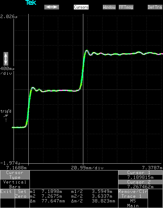
Open circuit
The step on the left is the pulse generated by the scope and the step in the middle is the reflection. I have told the scope to grade the horizontal axis in meters, so the scope tells me that Δm, the distance the pulse has travelled, is about 77.6mm. Since the pulse has travelled to the connector and back again, the length of the cable between the source and the connector is half of that, Δm/2, which is 38.8mm. Actually, the scope always measures time, the time between the two steps is about 370ps and assuming that the signal travels at 70% of the speed of light in the cable, the scope calculates that the distance travelled is 370E-2 * 300E6 * 70% = 77.6mm.
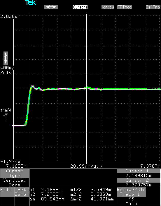
If I instead short the output, the pulse is shorted to ground at the end and the voltage of the reflected pulse is inverted, so the sum of the outgoing pulse and the reflected pulse is zero.

Short circuit
Note that the measured length of the cable is slightly longer, which is quite correct since the shorting plug I added to the end of the connector sticks out a bit so the signal has to travel a slightly longer distance.
There are no cables with infinite length, but it is possible to fake it by terminating a cable with a resistor having the same resistance as the characteristic impedance of the cable. Most oscilloscopes and coaxial cables used in a lab have a characteristic impedance of 50Ω, so putting a matching 50Ω terminating resistor at the end will absorb the pulse and there will be no reflection at all.
50Ω termination
Note that there is a bit of a bulge where the terminator is because the SMA connector on the scope or the terminator doesn’t have a perfect 50Ω impedance. With a perfect termination there would just be a flat line, but there are no perfect terminators either.
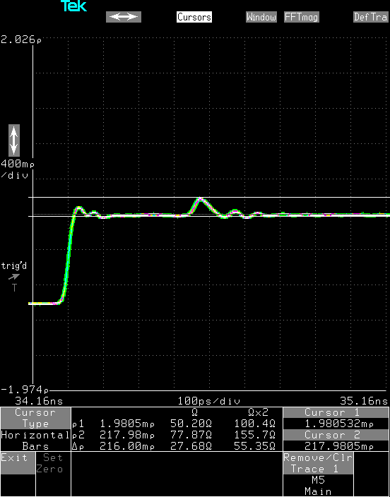
If the termination resistor is larger than 50Ω there will be a positive reflected pulse, but the voltage of the pulse will be less than with an open circuit. Here the output is terminated with a 100Ω resistor.
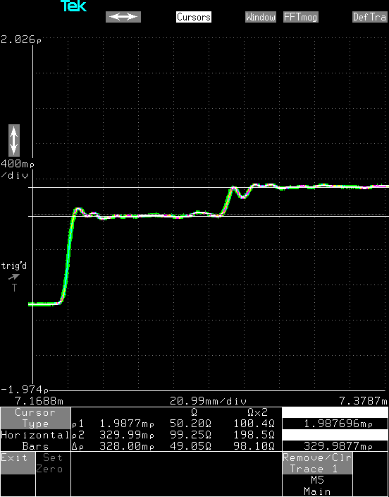
100Ω termination
The measured impedance of the cable inside the scope, ρ1, is about 50.20Ω and the measured impedance of the terminating resistor, ρ2, is 99.25Ω. Pretty good eh?
Similarly, with a smaller terminating resistance there will be a smaller inverted reflected pulse.
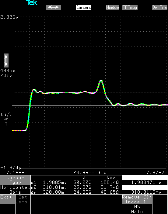
25Ω termination
The measured impedance of the terminating resistor is 25.87Ω.
It is quite important to tighten the SMA connectors properly. This is how the signal looks with the same 50Ω terminator when it hasn’t been properly tightened. Because there isn’t a proper connection the impedance becomes higher and a rather big reflection is generated, the measured impedance is 77.87Ω which is quite a lot.
Improperly tightened 50Ω terminator
One of the more practical uses of TDR is to measure the distance to a short or open circuit on cables. If I attach a matched 50cm long coaxial cable to the connector on the scope, the pulse will travel to the end of the cable before being reflected back. The end of this cable was left open, so the same reflection as with the open port is seen, just delayed a lot.
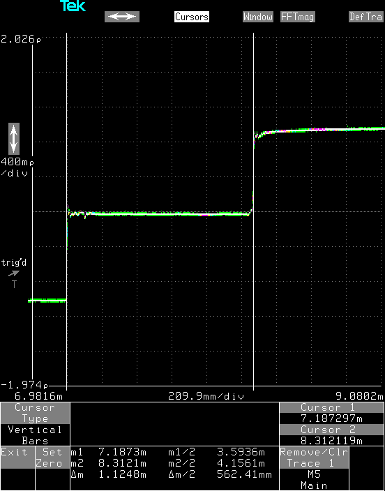
50cm of coaxial cable
The measured length, which includes the cable inside the scope, is 562mm which matches reality fairly well: about 40mm of cable inside the scope and another 500mm of coaxial cable outside. The measured length depends on the propagation speed of electricity in the specific kind of coaxial cable used, but normally it’s around 70% of the speed of light. With the exact propagation speed for a certain cable it is possible to get a much better distance measurement.
This kind of measurement is really useful when trying to figure out where a 1000 meter long buried cable has been damaged. With TDR it’s possible to measure the distance to the cut (or short circuit) with a good resolution, so the technicians trying to repair the cable will know exactly where to dig.
Imperfections on the cable will also show up as impedance changes and cause reflections. This is how a cable looks when it is being pinched hard.
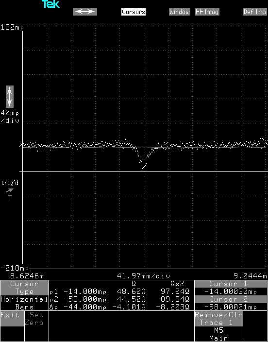
Pinched coaxial cable
Because the shield comes closer to the center conductor when pinched, the impedance becomes smaller. It’s not extremely bad, only 10% difference in impedance, but if this was a TV antenna, this could show up as a ghost image on the screen. In a high speed digital communications system, the reflection could be bad enough to corrupt data, or at least slow down transmission because a packet of data has to be resent. TDR can be used to find this kind of imperfections in a 1000 meter cable too.