SD Sniffer
I need to debug a problem with a SD bus. I have previously used a USBee SX with a custom firmware to sniff the bus and save a trace of all the SD signals to the hard drive so I could analyse them offline. This works fine up to about 30MHz but then the USBee runs out of bandwidth to the host PC. But the SD standard version 2 allows the bus to run at up to 50MHz and also tightens the electrical requirements for the SD bus, limiting impedance and capacitance so that the bus reliably can run at such high speeds. So for modern cards the USBee can’t keep up and the long wires to the USBee can introduce a bit too much loading and deteriorate the signals so much that the SD card will no longer work.
So I decided to build an adapter card which has a bunch of high impedance comparators sitting very close to the SD bus wires so that I can sniff the bus while changing the signals as little as possible. The signals will then be fed into an OpalKelly XEM3001 FPGA Board that I happen to have lying around. Anyway, since I have lost the source code that I used before to do the sniffing and analysis I have to rewrite everything anyway, so why not get a bit overambitious, I mean, what’s the fun in doing the same thing over again?
Time to fire up Eagle and throw together some schematics. The SD bus is available on a pin header on the board I’m debugging so I’m using the same pin header on my board. Then I’ve put a SD card holder on the PCB so that I can plug a normal SD card into it. Then there are a bunch of comparators, one for each signal on the SD bus, and then a D/A converter which gives the comparators a reference voltage to compare the SD signals with. The outputs from the comparators go to a another pin header which matches the ZBUS connector on the OpalKelly board. The comparators and the D/A are powered from the OpalKelly board.
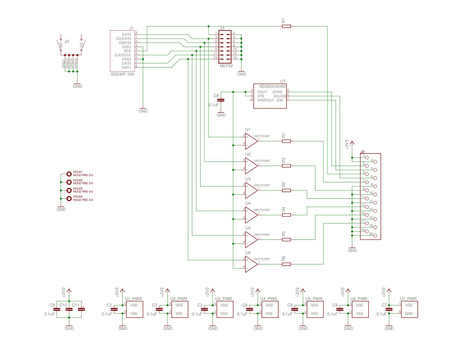
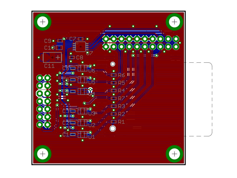
Next the PCB design. It did take quite a bit of time to squeeze everything onto a 2 layer board, but hopefully it’ll all work.
Some of the symbols and footprints I’m using are from the SparkFun Eagle library. I found the SD connector footprint on some forum on the net that I can’t manage to find again.
I then mailed off the gerber files to a PCB manufacturer and settled down to wait. 14 days later the finished PCBs arrived in the mail.
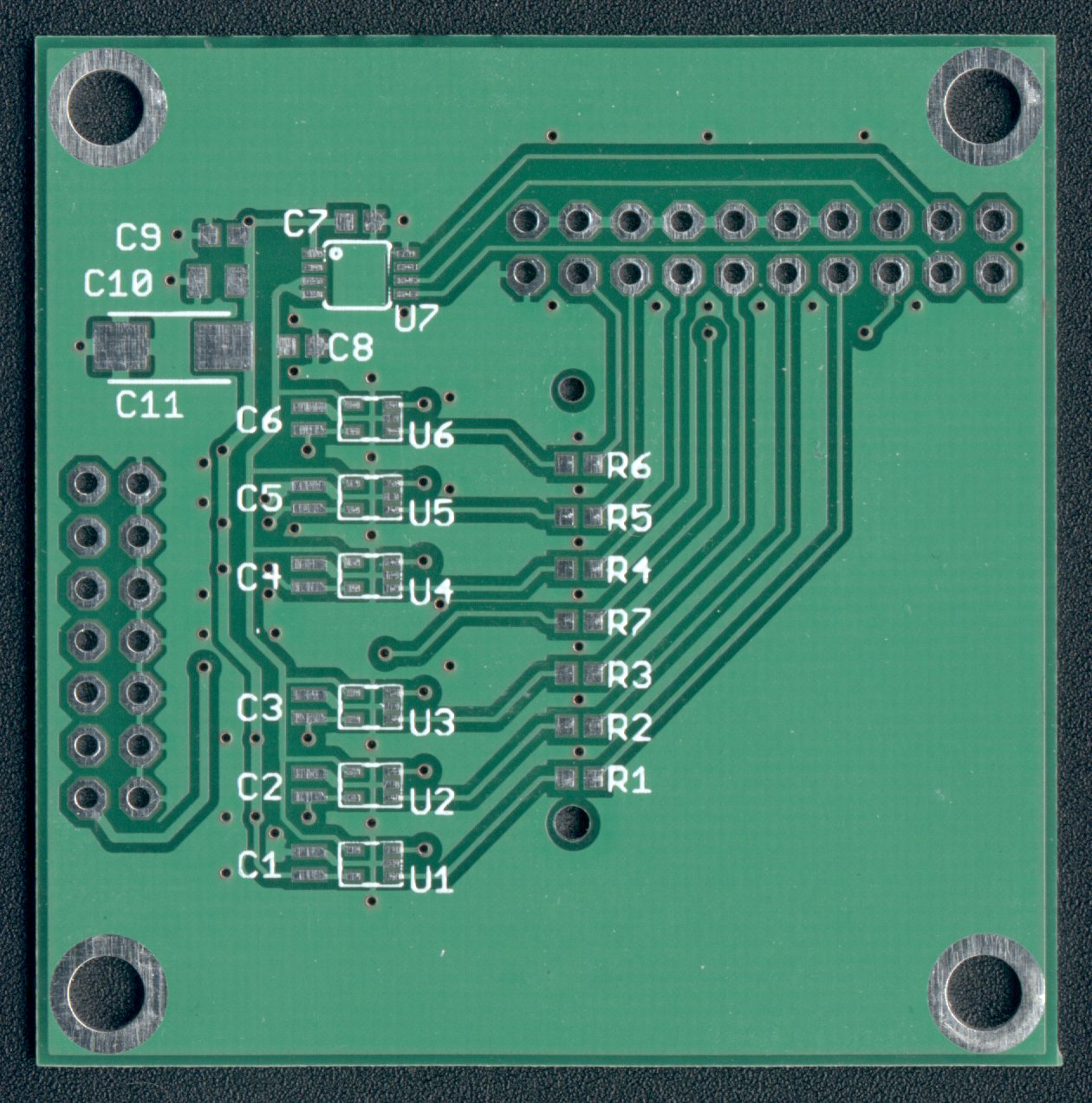
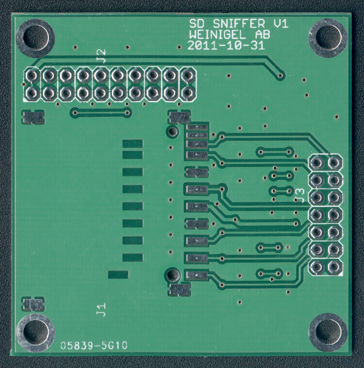
This is the first time I’ve used iteadstudio.com and the results look quite good, so I’ll definitely be using them again.
So the first thing I did was to solder the pin header and SD holder in place, and then put a SD card in the SD holder and plug the board into the SD bus, this way I could verify that the board would work as a plain SD extender:
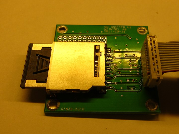
And it did! At least with an old an slow SD card.
So next up, test this with a modern high speed SD card running at 50MHz. And after that, start soldering some active components onto the board.
This post is continued in part 2.