Reverse Engineering, Part 1, Introduction
I like to do strange stuff with hardware, especially in combination with Linux. For example, I once bought an Acer n30 PDA. The PDA ran some variant of Windows CE so quite naturally I started poking at the device to see if I could get Linux to run on it instead. A few weeks I actually managed to get Linux to boot on it.
The process of figuring out how an existing piece of hardware works is called “reverse engineering” and I’d like to write a few words about how it’s done. I recently bought a RFID card reader that I wanted to figure out how it worked.
So, the first thing I did was to stick the thing in my scanner. Using a scanner is a pretty nifty trick to get good high resolution images of things. Most scanners has a very short field of depth, so it only works on fairly flat objects, anything that’s too far away from the glass will become very fuzzy. Luckily enough my old AGFA scanner has a good enough field of depth to work with PCBs so I get quite useful images out of it (click on the image for a larger version).
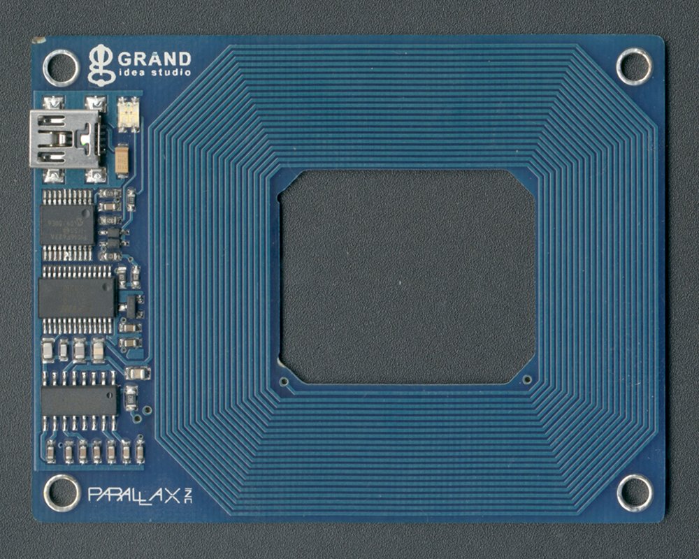
Parallax RFID Card Reader USB
Having a good image of the hardware is nice because it means I can print the image out on a piece of paper and make notes on it, and some details are just much easier to see in a high resolution image than in real life using a magnifying glass or a microscope.
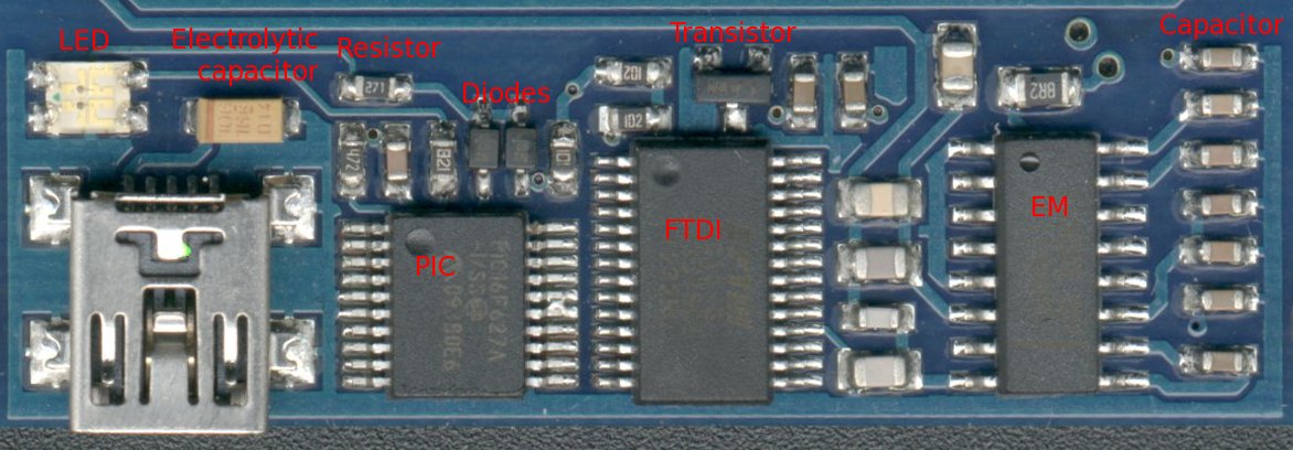
The next step is to figure out what the components are (click on the image for a larger version).
Identifying the Components
Some of the components are fairly easy to identify.
The clear thing to the left is a two color LED, fairly easy to figure out because it glows green or red when the reader is active.
The yellowish-brown component is an electrolytic capacitor, it’s just how they look. The brown line on the left end of it indicates the positive terminal.
The small black components are resistors and nicely enough the lettering on them is readable, so by just looking at the resistors it’s possible to see resistance it has, 271 means 27 with 1 zero tacked on at the end, so the resistance is 270 Ohm. 472 is 47 + 2 zeroes = 4700 Ohm or 4.7 kOhm. 8R2 is a bit special, it means 8.2 Ohm.
The other brown things with two terminals are usually ceramic capacitors. There is not lettering on them, so there’s no way to just look at one and see how big it is. But when reverse engineering things it’s usually not that important, I don’t have to know the capacitance, I just need to know that there is a capacitor there.
The diodes where a bit trickier, diodes come in many different shapes and colours. But by using the diode measurement on my multimeter I could see that the component was blocking current in one direction and that it had a voltage drop of about 0.4V in the other direction, so I could with confidence say that it is a diode with a 0.4V voltage drop.
The transistor was also a bit tricky. There are loads of components in exactly the same “SOT-23” package, among others diodes and reset circuits. Once again I was lucky because the lettering on top was visible and said “1AM”. A quick google search for SOT-23 + 1AM told me that it was a 2N3904 NPN transistor and also pointed me at the data sheet for it.
The big IC (integrated circuit) on the left is labeled PIC16F627A, and that’s exactly what it is, a Microchip PIC microcontroller and the data sheet is available from the manufacturer’s web page. Nice.
The second IC is a FTDI FT232RL USB-serial bridge. Once again the data sheet is available from the manufacturer’s web page.
The third IC was a bit harder to read, but with a magnifying glass and a good lamp I was able to see EM4095, which is a EM Marin “Read/Write analog front end for 125kHz RFID Basestation” and this sounds very plausible. And look, another data sheet, shiny.
So with all this done I have a nice picture of the board and I have a good idea of what all the components on the board are.